What Does L+C+R Mean? Decoding Circuit Fundamentals
Ever looked at a circuit diagram or heard engineers discuss components and wondered, "What does L+C+R mean?" You're not alone. These three letters represent the fundamental building blocks of virtually every electronic device around us, from the simplest flashlight to the most complex supercomputer. Understanding them is not just for electrical engineers; it's key to appreciating how our modern world functions. This article will demystify L, C, and R, breaking down their individual roles and explaining how they interact to create the dynamic and often surprising behaviors observed in electrical circuits. By the end, you'll have a solid grasp of these core concepts, empowering you to better understand the technology that shapes our daily lives.
In the realm of electronics, L, C, and R stand for Inductance, Capacitance, and Resistance, respectively. Each of these properties describes how a circuit component interacts with electrical current and voltage. While resistance might be the most intuitive for beginners, inductance and capacitance introduce dynamic behaviors that are crucial for understanding alternating current (AC) circuits, filtering signals, and storing energy. Let's embark on a journey to explore each of these pillars of electronics and see how they combine to form the intricate dance of electrons that powers our world.
Table of Contents
- The Foundational Trio: What Does L+C+R Mean in Electronics?
- Understanding Resistance (R): The Opposer of Flow
- Delving into Capacitance (C): The Energy Storehouse
- Exploring Inductance (L): The Current Stabilizer
- The Synergy of L+C+R: RLC Circuits Explained
- Resonance: The Heartbeat of L+C+R Circuits
- Practical Applications: Where Does L+C+R Shape Our World?
- Building Your Understanding: Tips for Grasping L+C+R Concepts
The Foundational Trio: What Does L+C+R Mean in Electronics?
When you encounter the phrase "what does L+C+R mean," you're looking at the core components that define how electrical energy behaves in a circuit. These are not just abstract concepts; they represent physical properties of components that engineers meticulously select and combine to achieve specific circuit functions. Imagine electricity as water flowing through pipes: resistance is like a narrow section restricting flow, capacitance is like a balloon that can store water and release it, and inductance is like a heavy flywheel that resists changes in flow. While this analogy simplifies things, it gives a good starting point for understanding their individual roles before we dive into their complex interactions.
In essence, L, C, and R are the fundamental passive components in electronics. Passive means they don't generate power; instead, they consume, store, or dissipate it. Active components, like transistors or integrated circuits, require external power to operate and can amplify signals or perform complex logical operations. But even active components rely heavily on the precise behavior dictated by L, C, and R to function correctly. Mastering these three concepts is the bedrock for anyone looking to understand or design electronic systems, making the answer to "what does L+C+R mean" a critical piece of knowledge.
Understanding Resistance (R): The Opposer of Flow
Resistance, denoted by 'R' and measured in Ohms (Ω), is perhaps the most straightforward of the three. It's the property of a material that opposes the flow of electric current. Think of it as friction in a water pipe: the narrower or rougher the pipe, the more resistance there is to water flow. In an electrical circuit, a resistor converts electrical energy into heat. This conversion can be intentional, like in a heating element, or an unavoidable side effect, like heat generated in wires. Every material has some resistance, though conductors like copper have very low resistance, while insulators like rubber have very high resistance.
Resistors are essential for controlling current and voltage levels within a circuit. They can be used to limit current to protect other components, divide voltage to supply different parts of a circuit with specific voltage levels, or even to generate heat. The value of a resistor is fixed and doesn't change with frequency, making its behavior predictable in both direct current (DC) and alternating current (AC) circuits, unlike inductors and capacitors.
Ohm's Law and Resistance
The relationship between voltage (V), current (I), and resistance (R) is famously described by Ohm's Law: V = I × R. This fundamental law states that the voltage across a resistor is directly proportional to the current flowing through it, with the constant of proportionality being the resistance. This simple equation is the cornerstone of circuit analysis and is used extensively to calculate unknown values in a circuit. For example, if you know the voltage applied across a resistor and its resistance value, you can easily calculate the current that will flow through it (I = V/R). Conversely, if you know the current and voltage, you can determine the resistance (R = V/I).
Understanding Ohm's Law is crucial because it provides the mathematical framework for predicting and controlling the behavior of current and voltage in circuits containing resistors. It's the first step in truly grasping what does L+C+R mean in a practical sense, as resistance forms the steady, constant element against which the dynamic behaviors of inductance and capacitance are measured.
Delving into Capacitance (C): The Energy Storehouse
Capacitance, denoted by 'C' and measured in Farads (F), is the ability of a component to store electrical energy in an electric field. The component designed to do this is called a capacitor. A capacitor typically consists of two conductive plates separated by a non-conductive material called a dielectric. When a voltage is applied across the plates, an electric field is created within the dielectric, storing charge. The larger the plates, the closer they are, and the better the dielectric material, the higher the capacitance.
Unlike resistors, capacitors do not dissipate energy as heat (ideally). Instead, they store it and can release it back into the circuit. This makes them invaluable for a variety of applications:
- Filtering: Smoothing out pulsating DC voltages (rectification).
- Timing: Creating delays in circuits (e.g., in timers).
- Coupling/Decoupling: Blocking DC current while allowing AC signals to pass, or vice-versa, to isolate different parts of a circuit.
- Energy Storage: Providing bursts of power, like in camera flashes or defibrillators.
Capacitors in AC Circuits
The behavior of capacitors becomes particularly interesting in AC circuits. In a DC circuit, once a capacitor is fully charged, it acts like an open circuit, blocking the flow of current. However, in an AC circuit, where the voltage is constantly changing direction, a capacitor continuously charges and discharges. This continuous process allows AC current to "pass through" the capacitor, even though no electrons actually cross the dielectric gap. The opposition a capacitor presents to AC current is called capacitive reactance (Xc), and it is inversely proportional to the frequency of the AC signal and the capacitance (Xc = 1 / (2πfC)). This means that at higher frequencies, a capacitor offers less opposition to current flow, and at lower frequencies, it offers more. This frequency-dependent behavior is critical for understanding what does L+C+R mean in the context of filtering and tuning circuits.
Exploring Inductance (L): The Current Stabilizer
Inductance, denoted by 'L' and measured in Henrys (H), is the property of a component to store energy in a magnetic field when current flows through it. The component designed for this purpose is called an inductor, typically a coil of wire. When current flows through a wire, it generates a magnetic field around it. If the wire is coiled, these magnetic fields reinforce each other, creating a stronger overall magnetic field. The key characteristic of an inductor is its opposition to changes in current flow. This opposition arises from a phenomenon called electromagnetic induction: when the current changes, the magnetic field changes, which in turn induces a voltage ( electromotive force or EMF) across the inductor that opposes the change in current (Lenz's Law).
Inductors are vital for:
- Filtering: Blocking AC while allowing DC to pass, or vice-versa.
- Energy Storage: Storing energy in magnetic fields, often used in switching power supplies.
- Tuning: Used in conjunction with capacitors to select specific frequencies, like in radio tuners.
- Chokes: Limiting current surges.
Inductors in AC Circuits
Like capacitors, inductors exhibit frequency-dependent behavior in AC circuits. In a DC circuit, an inductor acts like a short circuit once the current stabilizes (assuming ideal wire resistance is zero). However, in an AC circuit, the constantly changing current causes the inductor to continuously build and collapse its magnetic field, inducing a voltage that opposes the change in current. The opposition an inductor presents to AC current is called inductive reactance (XL), and it is directly proportional to the frequency of the AC signal and the inductance (XL = 2πfL). This means that at higher frequencies, an inductor offers more opposition to current flow, and at lower frequencies, it offers less. This opposite behavior to capacitors is what makes the combination of L and C so powerful for frequency-selective circuits, directly answering aspects of "what does L+C+R mean" in practical circuit design.
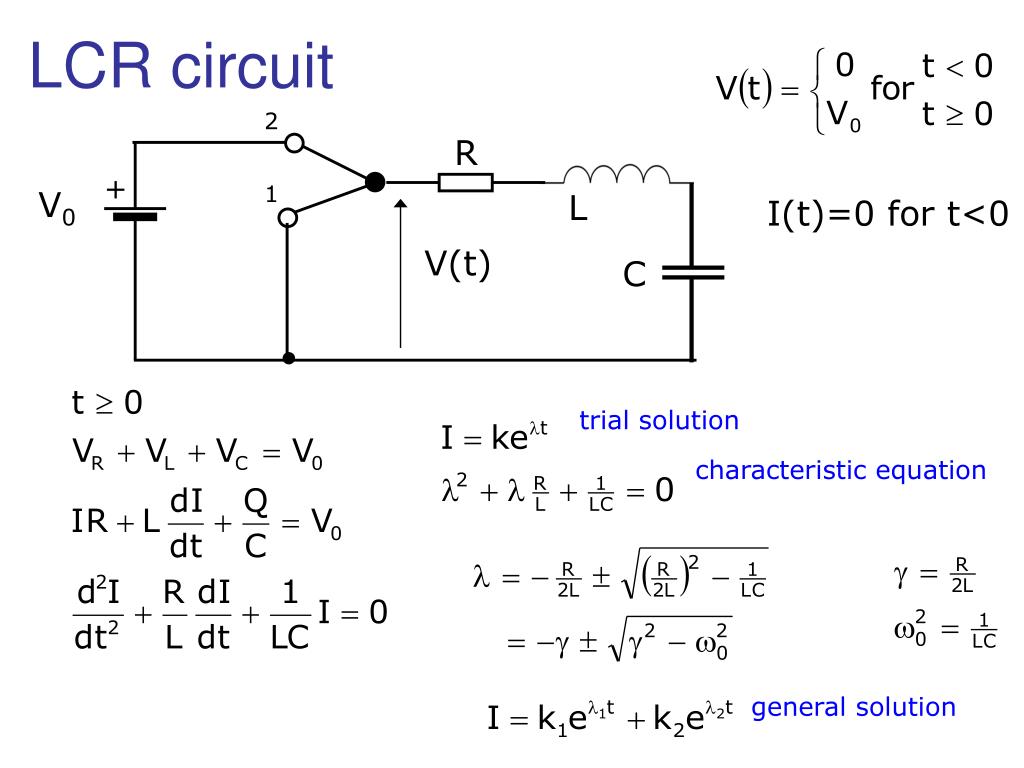
The Synergy of L+C+R: RLC Circuits Explained
While each component (R, L, C) has its unique behavior, their true power emerges when they are combined into RLC circuits. An RLC circuit contains at least one resistor, one inductor, and one capacitor. These circuits are fundamental to almost all electronic systems that process or generate alternating current (AC) signals. The interplay between the energy stored in the electric field of the capacitor and the magnetic field of the inductor, damped by the energy dissipation of the resistor, creates complex and often oscillatory behaviors.
In an RLC circuit, the total opposition to AC current is called impedance (Z), measured in Ohms. Impedance is a more general concept than resistance because it accounts for the frequency-dependent reactances of inductors and capacitors, as well as the constant resistance. The impedance of an RLC circuit is a vector sum of resistance, inductive reactance, and capacitive reactance, taking into account their phase relationships. Understanding impedance is paramount to understanding "what does L+C+R mean" in real-world applications, as it dictates how current flows and voltage drops across different components at varying frequencies.
Series vs. Parallel RLC Circuits
RLC components can be connected in series or parallel, each configuration leading to distinct characteristics:
- Series RLC Circuit: In a series RLC circuit, the components are connected end-to-end, so the same current flows through all of them. The total impedance is the vector sum of the individual resistances and reactances. Series RLC circuits are often used as band-pass or band-stop filters, allowing a specific range of frequencies to pass or blocking them, respectively.
- Parallel RLC Circuit: In a parallel RLC circuit, the components are connected across the same two points, so they all have the same voltage across them. The total impedance is calculated differently, often using admittance (the reciprocal of impedance). Parallel RLC circuits are commonly used in oscillator circuits and as notch filters.
The choice between series and parallel configurations depends entirely on the desired circuit behavior and the specific application. Both configurations leverage the unique properties of L, C, and R to manipulate AC signals in powerful ways.
Resonance: The Heartbeat of L+C+R Circuits
One of the most fascinating and crucial phenomena in RLC circuits is resonance. Resonance occurs at a specific frequency, known as the resonant frequency (f0), where the inductive reactance (XL) exactly cancels out the capacitive reactance (Xc). At this frequency, the circuit's impedance reaches its minimum (in a series RLC circuit) or maximum (in a parallel RLC circuit), leading to a significant increase in current or voltage, respectively. The formula for resonant frequency is: f0 = 1 / (2π√(LC)).
The concept of resonance is incredibly powerful and forms the basis for many electronic applications:
- Radio Tuning: When you tune a radio, you're adjusting the capacitance (or sometimes inductance) in an RLC circuit to match the resonant frequency of the desired radio station's signal. This allows the circuit to "select" that specific frequency while largely ignoring others.
- Filters: RLC circuits are used as filters to pass or reject specific frequency bands.
- Oscillators: They can generate continuous AC waveforms at a specific frequency, essential for clocks, signal generators, and communication systems.
Understanding resonance is central to truly grasping "what does L+C+R mean" beyond just their individual definitions. It's where their dynamic interplay creates predictable and exploitable electrical behaviors that are indispensable in modern technology.
Practical Applications: Where Does L+C+R Shape Our World?
The principles of L, C, and R are not confined to textbooks; they are the invisible workhorses behind countless technologies we use every day. Once you understand what does L+C+R mean, you start seeing their influence everywhere:
- Radio and Television: Every time you tune into a radio station or watch TV, RLC circuits are at work, selecting the desired frequency from a multitude of broadcast signals.
- Power Supplies: Capacitors are used to smooth out rectified AC voltage into stable DC voltage, while inductors can be found in switching power supplies to efficiently step up or step down voltages.
- Audio Systems: Crossover networks in loudspeakers use combinations of L and C to direct specific frequency ranges (low, mid, high) to the appropriate speaker drivers (woofers, mid-range, tweeters).
- Communication Devices: From mobile phones to Wi-Fi routers, RLC circuits are critical for transmitting and receiving high-frequency signals.
- Medical Devices: MRI machines, pacemakers, and defibrillators all rely on precise control of L, C, and R properties for their operation.
- Electric Vehicles: Inductors and capacitors play a vital role in power electronics for motor control, battery charging, and regenerative braking systems.
- Induction Cooktops: These appliances use high-frequency AC current passed through an inductor to create a magnetic field that directly heats compatible cookware.
This widespread application underscores the immense importance of these three fundamental properties. Without a deep understanding of what does L+C+R mean, the sophisticated electronic devices that define our modern era simply wouldn't exist.
Building Your Understanding: Tips for Grasping L+C+R Concepts
Grasping the nuances of L, C, and R, especially their dynamic behavior in AC circuits, can be challenging but incredibly rewarding. Here are some tips to solidify your understanding:
- Start with the Basics: Ensure you have a firm grasp of Ohm's Law and basic DC circuit theory before diving deep into AC. Resistance is the foundation upon which L and C build.
- Use Analogies (Carefully): The water analogy can be helpful for initial understanding, but remember its limitations. Electrical phenomena have unique characteristics.
- Visualize: Try to visualize the electric fields in capacitors and magnetic fields in inductors. Understanding where energy is stored helps demystify their behavior.
- Practice with Problems: The best way to learn is by doing. Work through example problems involving calculating reactance, impedance, and resonant frequency. Online calculators and simulators can be very useful here.
- Experiment (Safely): If possible, build simple RLC circuits on a breadboard. Observe their behavior with an oscilloscope if you have access to one. Seeing the waveforms change with frequency is incredibly insightful. Always prioritize safety when working with electricity.
- Break It Down: When analyzing complex RLC circuits, break them down into smaller, manageable sections. Analyze each component's role before combining them.
- Consult Reliable Resources: Refer to reputable textbooks, university lecture notes, and well-regarded online tutorials. Websites like All About Circuits, Khan Academy, and academic electrical engineering departments offer excellent resources.
- Don't Be Afraid to Revisit: These concepts can take time to fully sink in. If something doesn't click immediately, step away and come back to it with a fresh perspective.
By taking a structured approach and actively engaging with the material, you'll find that the answer to "what does L+C+R mean" becomes second nature, unlocking a deeper appreciation for the electronic world around you.
Conclusion
In summary, understanding what does L+C+R mean is fundamental to comprehending the vast majority of electronic circuits. Resistance (R) opposes current flow, dissipating energy as heat. Capacitance (C) stores energy in an electric field, opposing changes in voltage. Inductance (L) stores energy in a magnetic field, opposing changes in current. While each plays a distinct role, their true power lies in their interaction within RLC circuits, especially in the presence of alternating current. This dynamic interplay gives rise to phenomena like resonance, which is critical for filtering, tuning, and generating signals in everything from your smartphone to medical imaging equipment.
The journey to mastering these concepts is a rewarding one, opening doors to understanding the very fabric of modern technology. We encourage you to continue exploring the fascinating world of electronics. Dive deeper into specific applications, experiment with circuit simulations, or even try building a simple RLC circuit yourself. The more you engage, the clearer the intricate dance of L, C, and R will become. What other electronic concepts intrigue you? Share your thoughts in the comments below, or explore our other articles to expand your knowledge!

What Does L+C+R Mean on Instagram? - Buzzoid

Hello, what does L C R mean? thanks : NothingTech
PPT - LCR circuit PowerPoint Presentation, free download - ID:2856139
